 |
| Rear upper strut fitting (7V4-4) install at trailing edge of rib #3 |
Tuesday, May 12, 2015
Install port rear spar strut fittings (7V4-4)

Monday, May 11, 2015
Complete port rear spar channel installations
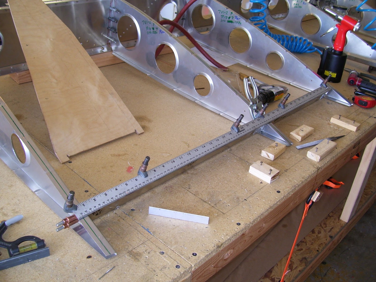 |
| Port wing rear spar channels |
Finished installation of the rear channel (spar) components.
Sunday, May 10, 2015
Started installation of rear channels to create rear spar
 |
| Rear channel (spar) installation) |
 |
| Rear channel (spar) installation |
Install the rear channels (prepared with the stb wing build) to create the rear spar. Used the template from the stb wing construct & same method.
Saturday, May 9, 2015
Port wing ribs installation
 |
| Port wing ribs behind the nose ribs. |
Install (silver) port wing ribs behind the nose ribs. Assure vertical placement with square.
Friday, May 8, 2015
Install port spar doublers & nose ribs
 |
| Port wing nose rib install (silver) |
 |
| Port wing nose ribs in place |
Using the station lines as references, installed the 3 front spar L-angle doublers at stations 480, 1160, & 2760. Installed all 6 nose ribs in their proper locations assuring vertical placement with square.
Thursday, May 7, 2015
Prepare fpr Port wing build
Collected all components for construction of the port wing. Labeled all parts and scribed all center-lines in preparation.
Wednesday, May 6, 2015
Fabricated wing wiring harnesses
 |
| Wiring harness parts |
 |
| Grounding busses |
 |
| Positive & Negative Busses |
22 AWG, 2-conductor, shielded (Radio Shack):
(1) 18' tail-light assembly connector to inst. panel
(2) 6' stb wing-tip light connector at wing root to inst. panel
(3) 6' port wing-tip light connector at wing root to inst. panel
(4) 6' AOA vane to port wing root connector
(5) 6' AOA vane port wing connector to inst. panel (indicator)
22 AWG, 3-conductor, shielded:
(1) 4' AOA indicator (inst panel) to buses
28 AWG, 5-conductor, shielded:
(1) 18' elevator trim servo to inst. panel & pilot stick grip
Subscribe to:
Posts (Atom)